- Home
- Research
- Nanobiophotonics
- Research results
- A microfluidic functional element for increasing the volume of droplets and uniting droplets
A microfluidic functional element for increasing the volume of droplets and uniting droplets

21.12.2022
Droplet-based microfluidic systems are well established in analytics and screening. The novel functional unit presented here can be integrated into such networks and offers the possibility to adapt the droplet volume to a microchannel with larger droplet volumes and to combine sample and reagent droplets.
Microfluidic systems allow efficient processing of chemical analyses and screenings with regard to the interaction of microorganisms/cells and active substances. Droplet-based microfluidics processes droplets as tiny reaction vessels in microfluidic networks. These networks are based on various engineering approaches, such as capillary tubing or channels with microfluidic chips. Depending on the type of network, the processed droplets have specific characteristic volumes, which are derived from the diameters of the microchannels. To extend the function and increase the throughput, it is necessary to interconnect these networks to larger process chains/process loops. For this, a volume adjustment of the droplets to the following network is needed. The self-controlling functional unit presented here offers this in the form of everything from simple addition to the possibility of combining active ingredients in the process.
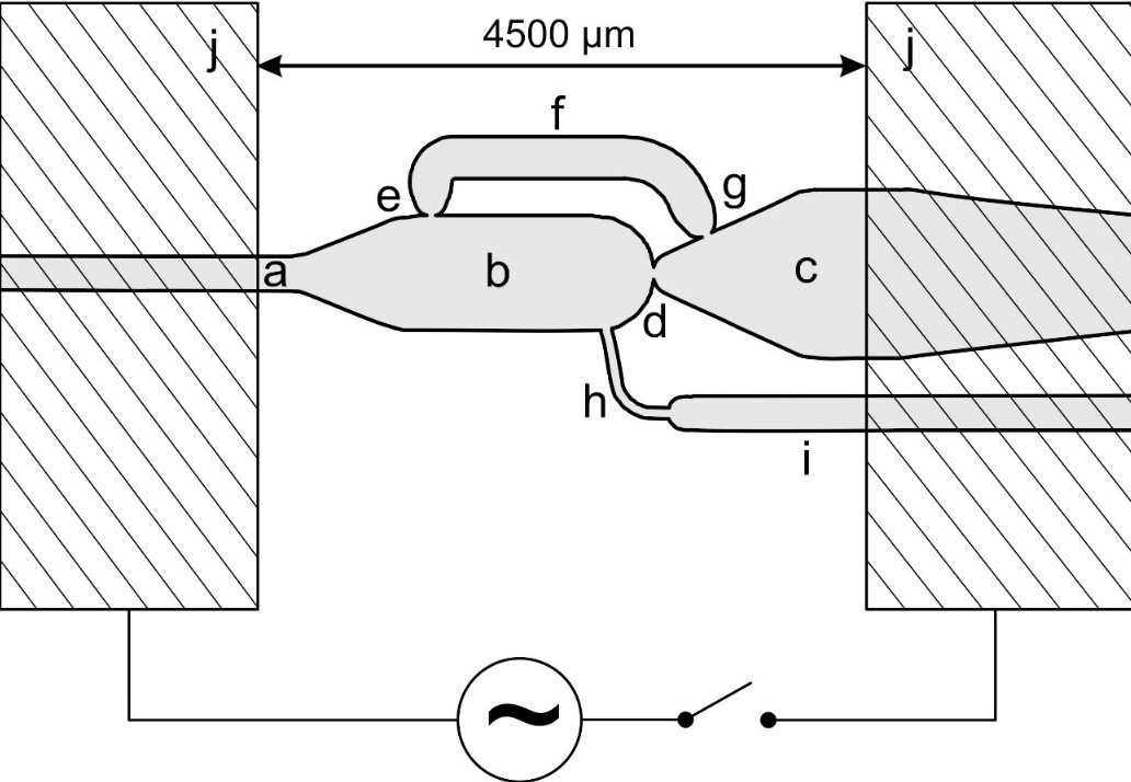
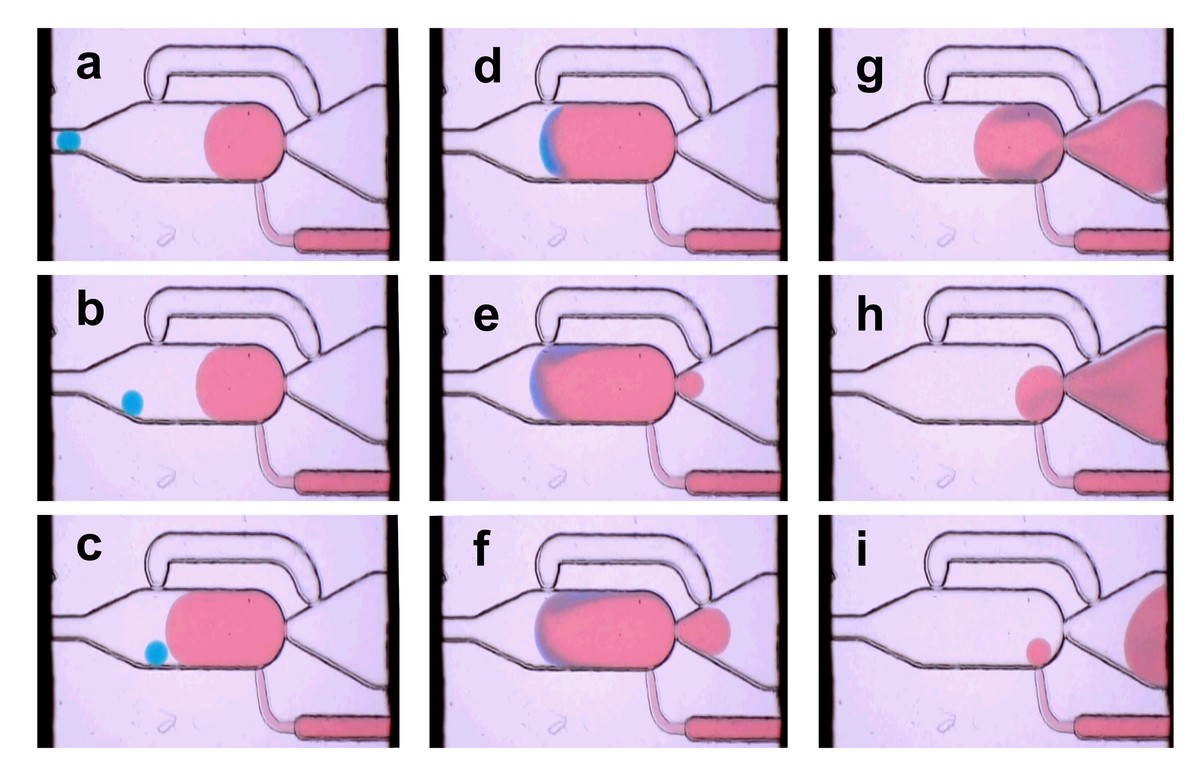
Droplet-based microfluidic networks consisting of many functional units, such as droplet generation, reagent addition, dividing, combining, and mixing into droplets operate in a self-controlling manner. This reduces the effort required to control the network and increases operational stability. The unit presented here uses nozzles and bypasses for this purpose, which are automatically closed or released by the droplets being processed. The forces for the switching operations are generated by the flowing liquids and by the surface tension of the phase interfaces between drop liquid and separation liquid. The functional sequence of the volume increase follows the sequence shown in the following image.

In the picture:
Cycle of a volume increase using the example of 2 droplets. a/b/c – the main chamber is filled from the left with a blue droplet. Continuously, separation medium (light) flows through the main chamber and via the bypass to the right to the outlet channel. A larger drop of buffer is already formed via channel i/h. d – under the influence of the alternating electric field, all drops combine on contact and mix. Meanwhile, buffer continues to be conveyed and the united droplet grows. d/f – the phase interface of the droplet moves towards the nozzle e of the bypass f due to its growth and closes it. As a result, the separation medium can no longer flow through the bypass, pressure builds up and drives the droplet through the main nozzle d towards the outlet channel. g – the funnel-shaped opening of the outlet channel forces the droplet to expand into the outlet channel after it has passed through due to the phase boundary surface tension. h – now the nozzle g of the bypass f is closed and the drop continues to be expelled from the main chamber. i – the main flow of the separation medium continues to drive the drop towards the outlet channel. At the same time, the drop is torn off from the inlet channel buffer i/h because of its inlet h, which is limited in cross-section. Here is the process as a video.
In addition to the adaptation of the volume, the functional unit offers the possibility of generating a concentration series. For this purpose, different numbers of drops together with correspondingly fewer buffers are applied to the target volume.
Another function is the introduction of combinatorics into a screening procedure, as often a microbiological response is dependent on several active substances. In this case, the volume of a droplet is not increased with buffer, but several droplets with different contents are combined into one droplet with target volume. The addition of buffer via channel i/h is not necessary in this process. This combination is then further processed in the follower network, making more complex self-controlling microfluidic networks possible.
In the image above:
Channel structure of the functional unit with electrodes (j, hatched). a – inflow channel, b – main chamber, c – outflow channel, d – main nozzle, f – bypass with nozzles e and g, h/i – inflow channel for buffer.
